Funded by European Union CIG-CSP3OCF3
Organocatalytic synthesis of fluorine compounds. Development of
new methodologies for the enantioselective introduction of fluorine
building blocks via CH activation of sp3 carbon
4. Photo-Reactors and Flow Chemistry
Photoreactor design
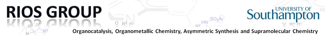
To facilitate the reactions we constructed two photoreactors, these are shown in Figure 1. Both photoreactors are made up of the same basic setup, a stirrer plate under a simple glass cylinder with a strip of green LED lights. The first photoreactor had a cylinder of a height of approximately 30 cm, this enclosed the latent heat of the LED’s, and therefore, a fan was placed on top to return the temperature in the reactor to room temperature (21-25oC). The subsequently constructed reactors were formed using approximately 8 cm tall cylinders, which did not suffer from the same drawback allowing the reaction to proceed at room temperature. The reactions were then run in closed glass vials placed evenly within the cylinder with no more than four reaction vessels per reactor.
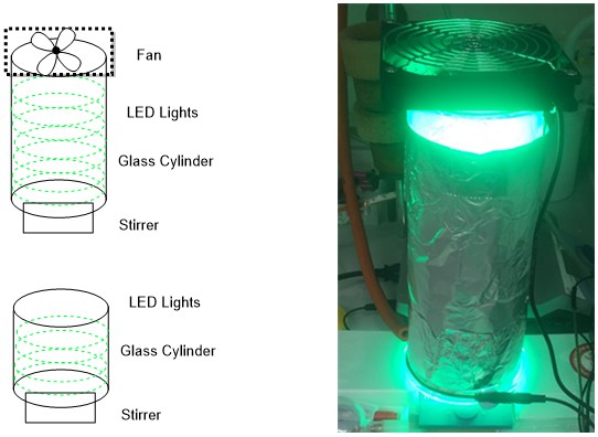
Figure 1- Schematic and photo of the constructed photoreactor for the methodology used in the projects outlined
The construction of the flow reactor was based upon a modified version of the protocol set out by Nöel et al. in 2015.[89] In that protocol, the reactor is constructed for the use of gas-liquid catalysis whereas the reactions presented in this thesis do not utilise gaseous reactants. Two reactors were constructed, the first step of both was wrap an appropriately sized cylinder with aluminium foil to allow for the refraction of the non-absorbed photons back into the tubing. Next the perfluoroalkoxy (PFA) tubing, with outer and inner diameters of this capillary of 1.58 mm (1/16 inch) and 0.5 mm respectively, was wrapped around the cylinder leaving 10 cm of tubing to allow for collection. This PFA tubing was specifically chosen as it has a high light transmission of 91–96% for visible light. Two lengths of tubing were employed 3m and 10m with total volume of 590 μl and 1.6 ml respectively. The calculation of the volume can be seen in the equation below, where vc is the inner volume, id is the inner diameter and L is the length of tubing.
Initially, the reactors were supplied with only one syringe but after optimisation using a polyetheretherketone PEEK cross micromixer (1/16-inch, i.d. = 0.5 mm) and two syringes was found to be superior. These were attached using PEEK nuts with the corresponding ferrules to the mixer and a luer adaptor for the syringes. The wrapped cylinders were then clamped horizontally, and then previously utilized LED wrapped glass cylinder was held equidistant for the tubing. The reaction mixture was collected in a foil wrapped beaker to ensure no further reaction could occur after the mixture had left the reactor. The flow rate of the reaction was controlled by an Aladdin2-220 syringe pump.
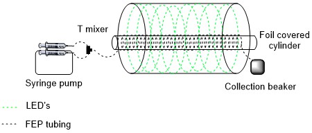
Figure 2 - Schematic of the flow set up
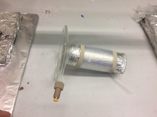
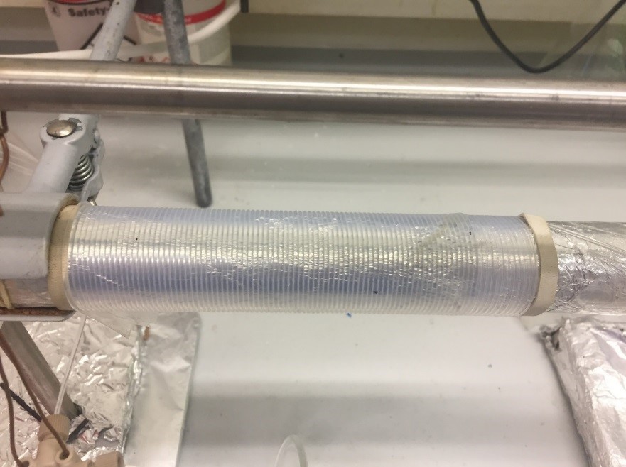
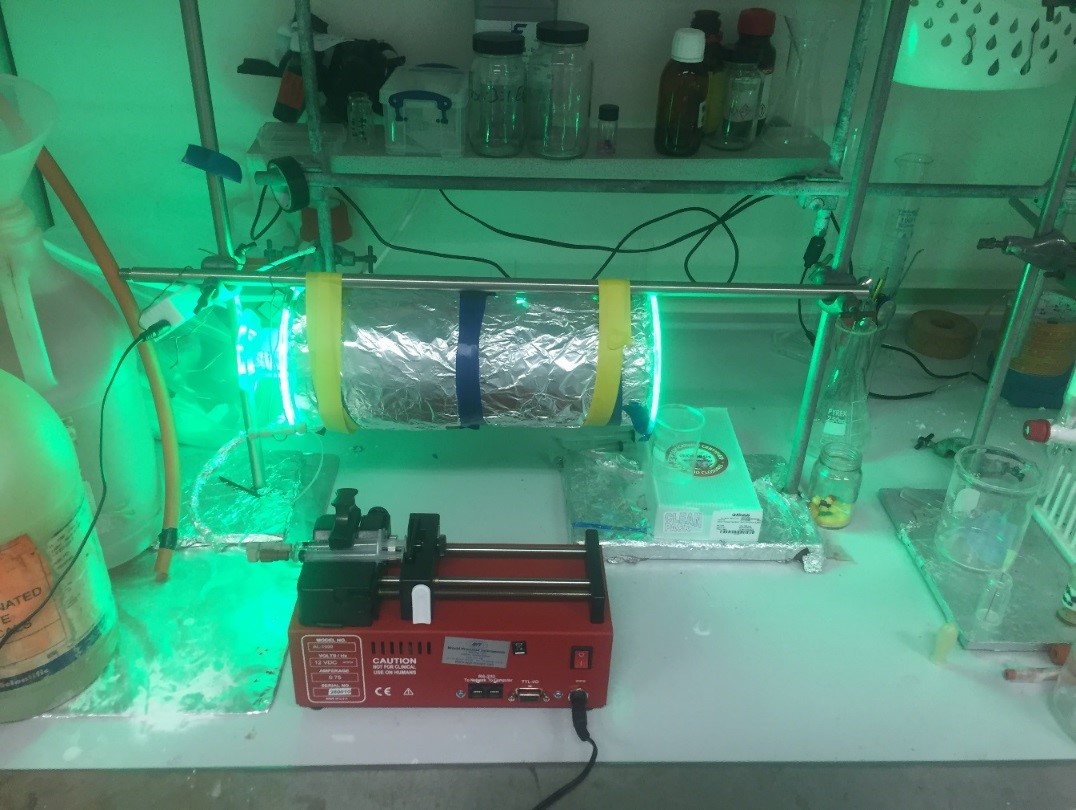
Figure 3 - up left) 590 μl reactor up right) 1.6 ml reactor down) fully constructed photoredox flow setup
Publications:
2- “Organophotocatalytic synthesis of phosphoramidates” Marta Meazza, Agnieszka Kowalczuk, Luke Shirley, Hao Guo* and Ramon Rios*.Adv. Synth. Catal. 2016, 358, 719-723.